Artificial reverberation, often shortened to reverb, is a commonly used tool by musicians, producers, and mixing engineers. Many auditory experiences are shaped by the acoustic environment in which they exist. When music could be captured in an acoustically dead space and then relayed over headphones, that sense of space is lost. Thus, engineers figured out how to put the space back into the sound. Without any physical constraints, reverb was transformed into a creative tool and applying it became an art of its own.
Previous Research
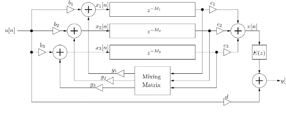
The feedback delay network (FDN) method for artificial reverberation was first proposed by Jot [1]. This structure uses a vector of delay lines (channels) that feedback into each other. Energy is distributed across these channels via the mixing matrix, preventing perceptually distinct delayed copies of the source signal. Thus, the many reflections that occur within a space can be emulated by a small number of delays. The FDN structure is more computationally efficient than convolutional or ray-tracing modelling of real-world spaces. To accurately mimic real spaces, however, a FDN model requires precise tuning of its parameters.
Diagram of the Feedback Delay Network structure
Another strength of the FDN is its flexibility. By altering the delay line lengths, scalar coefficients, and filters, a variety of room sounds can be emulated. Within this lies another weakness of the FDN: these parameters do not directly correlate to the physical properties of a real space.
Physical modelling of acoustic systems allows for synthetic results different to that of traditional synthesis forms (wavetable, additive). Given the potential complexity of such algorithms, computational optimizations were required for early implementations. The digital waveguide technique pioneered by Smith [2] allowed for synthesis of strings and wind instruments by solving for the output of travelling waves. These waves can be simulated by a simple delay line, where the length of the line corresponds to the pitch of the note.
Generalized waveguide networks offer a glimpse into how multiple waveguides can meaningfully interact [5]. Such networks allow for scattering junctions and optimized filters. In a piano, many strings interact through sympathetic resonance and unified bridges. Theoretically, the same principles could be applied to non-piano models and impart some of the key characteristics of a piano.
Motivation
Inspiration for this project came from my experience as a producer and mixing engineer. Artificial reverberation is a staple audio effect in all my projects. Over the last thirty years of FDN implementations, developers and designers have created both complex and simple reverbs for any musical situation. Understanding the potential (and the limits) of reverb would help me apply these tools more effectively.
Given the abundance of existing reverb algorithms, I sought to incorporate some of the concepts we learned this semester into a novel audio effect. At the core of the FDN structure is the vector of delay lines. Delay lines are a key data structure found in digital waveguide models, pitch shifters, flangers, and many more. One device I like is Ableton’s Resonators tool. With five tunable resonators, incoming signals are fed into the feedbacking delay lines to blend in the harmonics of a chord.
In addition to simulating acoustic instruments, the principles of physical modelling and digital waveguides can produce unique and organic sounds. I personally use the tools developed by
Applied Acoustic Systems
and
Plasmonic by Rhizomatic
in my musical endeavors.
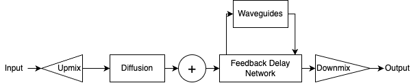
Originally, I envisioned a hybrid reverb-resonator that would blend FDN delay lines with digital waveguide delay lines to create a tonal and dispersed sound. At this point in the process, I did not know what I was doing or whether this was feasible.
Envisioned structure for the Hybrid Waveguide Reverb Network
Development
The first step was to implement a FDN reverb in C++ using the JUCE framework. While JUCE already has a basic reverb object, I wanted to create my own to give flexibility over the structure and to cement my knowledge on the subject. The work of Geraint Luff and Will Pirkle [4] were valuable resources.
At the core of the reverb is a sixteen-channel FDN with a
Householder
mixing matrix. Each channel has a different length, calculated from a room size parameter. With a room size of 150ms, the delay line lengths range from 6,600-13,000 samples, and with a room size of 300ms the delay line lengths range from 13,000-26,000 samples. The feedback amount (or decay coefficient) is calculated from an RT60 parameter.
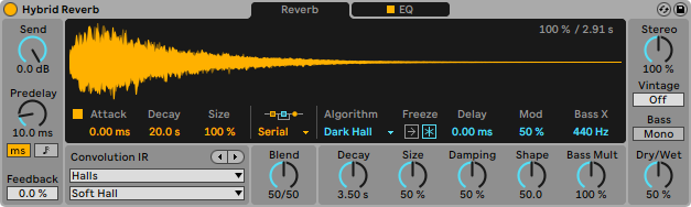
The FDN structure is effective at mimicking late reflections but struggles to imitate the early reflections that occur right after the source signal enters the network. One common solution is to use a short impulse response to diffuse the signal first. By using an impulse response of 2048 samples (46 milliseconds at 44.1kHz sampling rate), the lesser computational burden is balanced with the increase in sound quality. The Hybrid Reverb device in Ableton Live offers this functionality, providing a selection of impulse responses and FDN structures that can be intermixed.
Ableton's Hybrid Reverb interface
If convolution is to be avoided, allpass filters can be used. Schroeder determined that large echo density and flat frequency response were key to believable artificial reverberation. A Schroeder allpass filter is an IIR filter with a feedback loop and feedforward path. The feedback loop creates a comb filter, and the feedforward path allows for the flat frequency response. By nesting allpass filters, more complicated reverberation sounds can be produced.
An alternative approach is to design a network of shorter, non-feedbacking delay lines. Just like an allpass filter, a delay line has a flat frequency response. To create diffusion rather than perceptible echoes, shorter delay line lengths are used, varying from 44-13,000 samples (1-300 milliseconds). The maximum delay line length is determined by the room size (while for the FDN, the room size determines the minimum delay line length). A mixing matrix can provide additional diffusion by distributing input signals evenly across the output channels. I’ve opted for a
Hadamard
matrix instead of the Householder matrix used for the FDN. To increase the amount of diffusion, this process can be performed multiple times in series. The first diffusion step we’ll set to shorter delay line lengths, and each successive step will have increasing lengths.
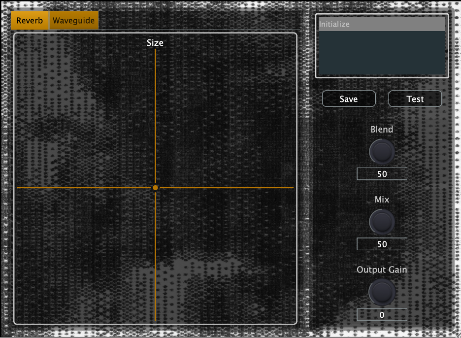
The user can control the room size and the RT60 with the “Size” X-Y grid.
The process of upmixing one or two input channels up to the number of delay lines in the diffusion and FDN structures (16 in this case) can be as simple as duplicating the input signal. Since each delay line is of a different length, each output channel will provide a distinct result. Likewise, when downmixing from 16 channels to two channels, we could just sum half the input channels into L and half into R. A more inspired approach involves calculating a set of coefficients from sine and cosine function. The phase increases from 0 to pi: even channels are assigned the output from sin(phase) and odd channels the output from cos(phase). The first to channels are set to 1 and 0 respectively. These coefficients are used for upmixing and downmixing.
With the reverb completed, work on the waveguide network began. First, I implemented a waveguide plucked string. The string contains two delay lines, one for forward propagation and one for backward propagation. My circular delay line object from the reverb was used. For each output sample from the string, the outputs from each line are filtered through one-pole allpass filters. Then, the output from the backward line is inverted and fed back into the forward line, while the output from the forward line is inverted, multiplied by the decay coefficient, lowpass filtered, and fed into the backward line. The pickup position determines where in each line the new samples are extracted. These samples are summed and fed through a filterbank of 16 biquads that estimate the modes of a violin body, and that produces the final result.
The strings are plucked with a velocity that adds a linear ramp to both the forward and backward delay lines. The ramp goes from zero to the velocity (or -1 times the velocity) and has a duration determined by the trigger position.
To match the 16 delay lines in the reverb, 16 waveguide strings are collected into a new object. After the input audio is upmixed to 16 channels, each channel that exceeds a threshold can trigger its corresponding string with a velocity of the amplitude. The string is triggered after a certain number of cycles have passed. The number of cycles is set by the “rate” parameter and varies slightly such that the strings are out of sync with each other.
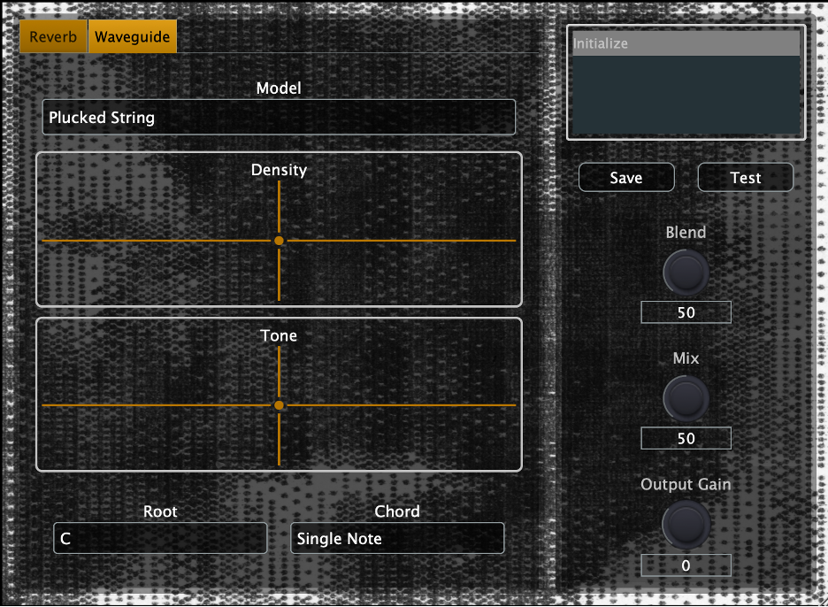
The user can control the decay coefficient and rate factor with the “Density” X-Y grid, and the pickup position and trigger position with the “Tone” X-Y grid.
Two drop down menus allow the user to select a root note and chord type for the waveguides. The “single note” option tunes all waveguides to the selected root note. The other chords (Major, Minor, Dominant, Major 7, Minor 7) tune the strings to the notes in that chord. For example, with the root note of C, and the Major chord selected, four of the strings are tuned to C3, four are tuned to E3, four are tuned to G3, and four are tuned to C4.
The "Blend" knob mixes between the reverb and waveguide mixes, and the "Mix" knob controls the level of the wet (output) signal compared to the dry (input) signal.
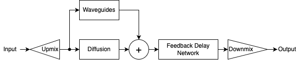
Diagram of the current Hybrid Waveguide Reverb Network structure
Interface
Note: the “play” and “test” buttons trigger an audio loop for testing and debugging purposes, it will be removed in the final product.
Prototype interface
"Final" interface (subject to change)
Demo Video
Issues Faced
I’m always learning new things in JUCE and C++. This project, I opted for some new coding practices and modules to (theoretically) improve the result. As a result, my attention was often diverted away from the DSP.
I used the
Pamplejuce
template developed by Sudara as a starting point for the project. This GitHub repo is designed to streamline some of the less enjoyable aspects of the JUCE building process. JUCE provides a compiling tool called Projucer for file and build management, but regular CMake offers extra functionality. Thus, the Pamplejuce template functions well with the CLion IDE by JetBrains which integrates well will CMake for C++ application development. I have also never used CLion before, but I already prefer it to Xcode most of the time.
Designing and implementing GUIs in JUCE is generally the most time-consuming stage of the development process. While I have become more efficient over the past few years, it is still a frustrating experience. The
FoleysGuiMagic
module developed by Daniel Walz adds a GUI for making your own GUI. Building your GUI visually is more satisfying than placing elements in code and hoping they line up well. Setting up the module and adding complex functionality, however, was less straightforward than I hoped (especially when adding elements I already knew how to implement without the module). Luckily, Daniel was regularly available on Discord and able to help when I ran into issues.
Conclusions and Future Work
I learned a lot during this project. I have yet to learn to not overestimate my abilities and the time required for a JUCE project.
I should have spent more time and effort brainstorming how the waveguide and reverb delay lines would interact. Initial prototyping in Matlab might have made more sense than jumping right into C++. The article "Generalized Digital Waveguide Networks" [5] gives insight into acoustic parallels of a network of digital waveguides. One example given is piano strings attached to a common bridge which allows for coupling. Another application could be sympathetic vibrations, like those that exist in a guitar or piano.
I would like to incorporate more digital waveguide models, especially models that have a sustained sound. A bowed string would be my priority, then wind instrument models. In addition to more control over the waveguide model, I would implement more body filters. Currently, the violin body filter is hardcoded, but with some other filters, the user could control which filter is applied.
Another missing key feature is MIDI input to control the pitches of the waveguides. This way, the musician can tune the waveguides to match the harmonic content of the input audio more easily than automating the root note and chord parameters.
Some nice-to-have features include better waveguide trigger detection via filtering and octave selection for the root note. The reverb sound could also be improved to have different structures and more options.
This device needs a variety of improvements before it provides meaningful value in a music creation process. Ideally, I would feel proud to release this either as open-source code or for commercial release, but I do not feel that way in its current state. It will require a combination of signal processing changes, a GUI refresh, and thorough validation testing.
[1] Jot, Jean-Marc, et al. “Analysis and Synthesis of Room Reverberation Based on a Statistical Time-Frequency Model.” In Proceedings of the 103rd Audio Engineering Society Convention, 1997.
[2] Smith, Julius O. “Physical Modeling Using Digital Waveguides.” Computer Music Journal, vol. 16, no. 4, 1992, pp. 74–91. https://doi.org/10.2307/3680470.
[3] Gardner, William G. “Reverberation Algorithms” from Applications of DSP to Audio and Acoustics. 2002.
[4] Pirkle, Will C. Designing Audio Effect Plugins in C++ : for AAX, AU, and VST3 with DSP theory. Second Edition. New York, NY. 2019.
[5] Rocchesso, David and Smith, Julius O. “Generalized Digital Waveguide Networks” in IEEE Transactions on Speech and Audio Processing, vol. 11, no. 3. 2003.